By Steve Cragg, VP of Sales and Marketing
Introduction
Analog radio systems still make up a significant portion of public safety radio systems in the US and historically most used copper (leased) lines for connectivity between sites. These copper lines have provided a secure and reliable means of connectivity for decades.
Over recent years the providers of these lines have decided to remove their leased line service which has led to a sharp reduction in reliability and high down times. Additionally, the providers are either simply removing the service, or dramatically increasing the cost of leased lines, both of which leaves users considering what to do to replace this service. The solution must ensure continued operation of the system at its current reliability and at a reasonable cost which is why many users are considering IP as an alternative to leased lines. Recent studies have shown that the average small to medium radio user will save in excess of $50,000 by switching to an IP based backhaul solution using commercially available ethernet.
Unfortunately, analog systems do not interface directly to IP systems and there are a number of considerations to examine when doing so.
This paper discusses three of the most critical considerations:
- Redundancy
- Latency
- Audio Clarity
In addition, this paper will cover strategies to mitigate migration challenges to ensure the long term reliable operation of your system is maintained.
Redundancy
Redundancy is a critical consideration when considering using IP connectivity.
In analog radio systems, individual links connect to channels on specific sites, so the loss of a single leased line simply affects one repeater or voted receiver. However, with IP, the system is routed through a single ISP head end, so the site connectivity and whole system can be impacted if connectivity is lost and the system is not properly designed.
While the option to duplicate everything in the network for redundancy may seem to be sensible, the cost benefit of such an approach does not always pencil out.
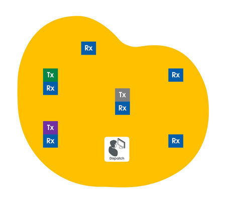
Consider, for example, how to mitigate the loss of IP connectivity during failure of a single part of the system. In this example we will consider a simplified six-site simulcast system with three repeater sites and three remote receivers. Let's assume all sites are put through a voter back to the dispatch center and the dispatcher can transmit on all three simulcast repeaters.
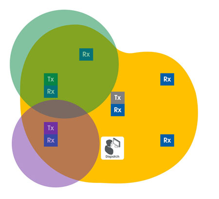
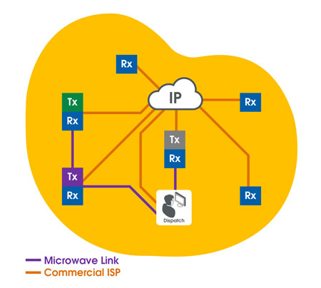
The system diagram is as follows, with the coverage area shown in yellow.
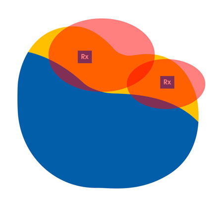
The Transmit coverage is as follows, with the color of the site transmitters shown overlaying the coverage area.
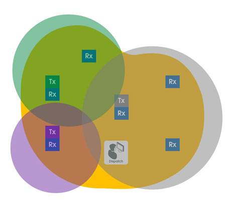
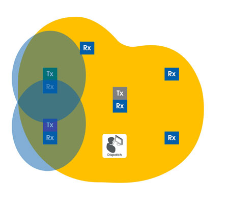
The receive sites provide coverage as follows:
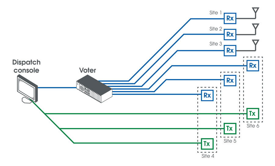
From a block diagram point of view, the system layout looks as follows:
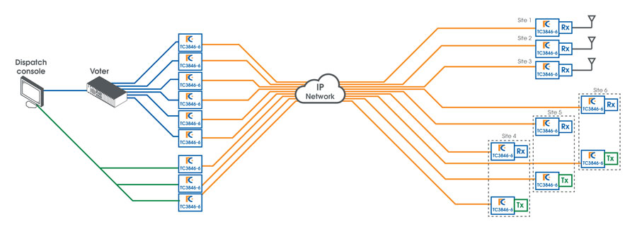
When we consider the conversion to IP, the system will require additional equipment to interface between the analog equipment and IP network which can be commercial or private.
In the diagram below we'll assume the TC Communications Jumboswitch TC3846-6 card will provide the interface to the legacy analog equipment such as the voters, transmitters and receivers and eliminate the need for copper circuits (leased lines) which will alter the diagram to look as follows:
In doing this, it is important to consider the failure mechanism for the system as it will be somewhat different from the original system. To do this, we should consider a few IP system configurations:
Ring vs. Bus
In a ring, if a link is broken or fails, sites still have connectivity, which is known as a 'self-healing ring'. Dispatch would connect to the remote sites and then the last site would connect back to dispatch to form a ring. This configuration is significantly more robust than a linear microwave system connecting the sites where the network starts with dispatch on one end and ends with the final remote site on the other end.
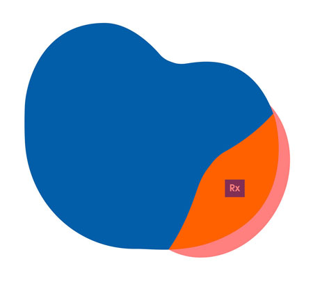
While a bus topology provides the same basic connectivity as the previously mentioned ring, loss of an individual link can have a significant impact on the network. For example, if the link between site two and three fails, connectivity is lost to sites three through six, significantly impact the operation of the system. While this may seem to be a sub-optimal configuration, it is commonly found in simple microwave systems designs, and would result in a reduction of system coverage to the following:
Transmission coverage
Receive coverage
This event would result in failure of the link between dispatch and site one, which would cause complete system failure.
In this instance a ring is far more reliable than the layout shown in the second example, but also more likely to be far more expensive to build. While it is preferable to have a system configuration that provides complete redundancy, it may not be possible due to land and construction constraints, cost and other limitations.
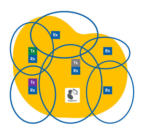
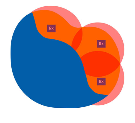
A hybrid configuration that does not have the cost of a complete ring may need to be considered, where the failure of a link has minimal impact to system operation, such as the following example:
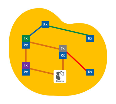
In this example failure of any of the orange links will not cause a system failure which protects the connectivity to the dispatch center and the transmit sites. Failure of a blue, green or purple link will cause a loss in the receive coverage as follows:
Failure of Blue Link
Failure of Purple Link
Note that unlike copper networks, failure of an individual link will affect all channels on that site which will need to be considered when determining impact of a link loss.
In addition, we'll need to consider how commercially provided IP network services are typically delivered. Most utilize a series of geographically disperse head ends, however, given the relatively small coverage areas of many radio systems it is not uncommon for IP connectivity to be provided from a single head end, which creates a single point of failure for the entire system.
This impact can be mitigated in several ways:
- Establishing an SLA requiring the provider to maintain the service to an agreed level.
- Requiring the provider to maintain connectivity to two or more head ends that are geographically diverse allowing failover such that loss of one does not impact the entire system. While this is technically a very good solution, it can be expensive to deploy.
- Strategic IP redundancy of key links throughout the system. Although this approach does have some cost associated, it can ensure that an isolated loss in the system will not result in total system failure.
Selection of critical links and cost benefit
The choice of where to provide duplication is very similar to the selection of other elements of the system. For example, in the system diagram below failure of the voter will cause the system to fail completely.
The voter itself is typically divided into racks and cards, so failure of a single rack or card results in partial failure of the system, but if power to the voter is removed, the entire system will fail. This makes the voter an excellent candidate for redundancy, such as redundant power supplies or battery backup, which is the same for the IP network.
Failure of the IP connectivity to the central site will cause complete system failure, making it an excellent candidate for redundancy
In addition, prioritization of sites in key. Even if a site is deemed critical, it may not be sensible to duplicate the IP connectivity to it. Consider the case of a site that provides only one voting receiver, which could result in the following modes of failure:
- Antenna loss
- Receiver loss
- Voter card failure
Each of these provides a failure exactly similar to an IP failure for that site. Given this, and the SLA provided by the provider, an IP failure in a hybrid design as shown above may result in less down time than a receiver failure that would require on site repairs to equipment that is a single point of failure.
An example hybrid system could be designed as follows:
In this case the microwave system provides primary IP connectivity between the transmit sites and the dispatch center. In the event of any failure of any of the microwave links then the IP network provided by the commercial provider will ensure redundancy. Failure of any of the IP links to the sites not connected to the microwave system will result in that site dropping off the network. Complete failure of the provider will result in only the remote receiver sites failing, as shown in the following diagram.
The same effect can be achieved by utilizing either an alternate provider for redundancy at the critical sites, or ensuring that the provider connects to diverse head ends.
Latency in Analog systems
While latency or delay is a part of any link for a radio system, the introduction of IP based links can introduce more latency, known as latency variation.
While voted analog systems are sensitive to delay in links, most voters have simple bulk delays that allow the user to adjust the system so that all the audio on the links arrive at the voter simultaneously.
Similarly, in simulcast, latency is important on the transmit path and only very small latency variations can be allowed. While many analog systems do allow for retraining of links, this can be a slow process and requires the system to be unusable during that time. With IP links, if there are significant latency variation, then this will cause significant distortion in the simulcast overlap zones, which can be avoided by choosing a solution with zero or minimal latency variation.
Low latency links with high audio clarity consume more bandwidth than a simple voice over IP (VoIP) link. The most common cause of latency variation is due to Packet Delay Variation (PDV), which is not as easy to address as it cannot simply be compensated for with the addition of bulk delay. Products that can compensate for PDV using a buffer to ensures the overall delay in the link is constant allows it to function exactly as a standard copper link.
Link delay will have a minimum value equal to the IP link delay when using wireless (4G) links, microwave links or others which can often range 40-100mS or satellite links which can be as high as 400mS. However a well-designed IP link can achieve a commercial network latency of under 10mS with little or no latency variation.
It's equally important for a system to pass control tones such as push to talk (PTT) control and voting tones as part of the audio. Many systems using VoIP or other digital formats utilize a tone detection and regeneration mechanism which introduces both phase and time delays into the system and may cause integration issues.
Audio Clarity
In comparing analog and digital transmissions, there are significant tradeoffs. On example is shown in the graph below showing the tradeoff for signal to noise ratio (SNR).
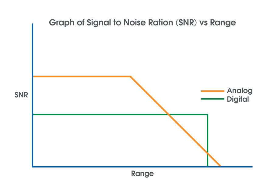
Analog systems generally have a better SNR when the received signal strength is high, however as the range increases the signal strength reduces resulting in a SNR that becomes proportional to range. In contrast, digital systems have a better SNR for a longer range due to digital transmission and error correction which results in a constant SNR over the whole range, albeit at a lower level than an analog system in a good coverage area.
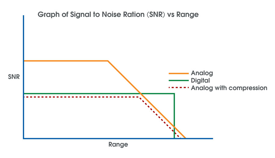
This is one of the inherent benefits of analog systems and consequently challenges of migrating to a digital system, maintaining audio quality. The digital audio being compressed to fit the 6.25kHz equivalency requirement, this compression removes some of the clarity compared to analog. This compression can degrade signal noise across the system which results in the worst characteristics of the two systems as shown below.
Compression can also eliminate or significantly attenuate control tones. Many digital standards are optimized for speech and do not consider the frequency of the control tones which are typically close to the edge of the audio frequency range. To mitigate this issue consider the audio bandwidth versus attenuation across the entire frequency range, not just the range for speech, which is a differentiating characteristic provided by the TC3846-6.
In summary, it is important to ensure that you select a device to provide audio clarity with no introduced compression in the link to maintain the standard of operation of the installed system operation.
Conclusion
While many users are converting to IP links to provide connectivity for analog radio systems, the use of IP will be accompanied by a number of design changes and challenges to integrate legacy links.
Consideration should be given to:
Redundancy
- Ensure that failure of the IP system does not unduly impact the operation of the radio system by using an appropriate redundancy configuration.
- Consider the appropriate redundancy scheme to maximize cost benefit ensuring savings are realized from the new solution.
Latency
- Latency affects both conventional voted and simulcast systems and is a key consideration to any system transition.
- Consider a low latency solution to provide the best in field operation; as long as the latency is consistent longer latency can be tolerated.
- Low or zero latency variation is key to successful operation, particularly for simulcast, but this is also important for voted systems.
Audio clarity
- Consider audio clarity in your selection of equipment to keep the best of the analog radio system. Full bandwidth operation is also particularly necessary when considering control and voting tones as digital compression can interfere with operation of these solutions.
- If compression is used to minimize the bandwidth, then the user can witness the audio sounding somewhat muffled which can be eliminated by utilizing a solution with a full bandwidth such as the TC3846-6.
Ask a question