By Steve Cragg, VP of Sales and Marketing
This white paper looks at the use of C37.94, which is a fiber-based protocol, in Teleprotection schemes between relays in a utility network. Because it is fiber-based, there is a single fiber in each direction—one each for transmitting and receiving data. As will be shown, it is essentially synchronous serial communication, but because it is fiber-based, there is no external clock circuit; rather, the clock is embedded and recovered from the data stream.
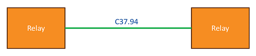
A C37.94 Example with Two Relays
In this example, there are two relays connected by C37.94. Data is being transmitted backwards and forwards between them on the two fibers of the C37.94.
C37.94 has a relatively high data rate of 2.048 megabits per second, so the issue with not using synchronous data is that it is very easy for the data to get out of synchronization and, consequently, be corrupted. So, C37.94 embeds the clock into the data stream so that the clock can be recovered at the receiving end, which preserves the validity of the data.
This is how it works. When looking at a regular string of data…
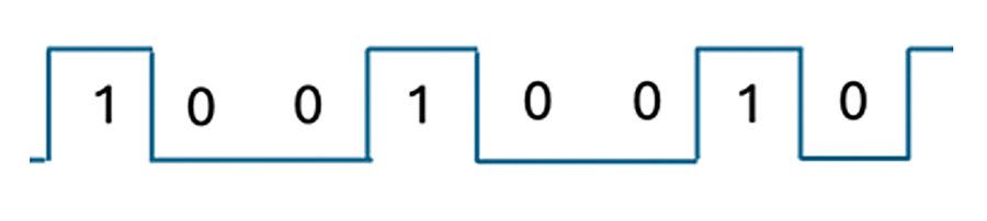
How C37.94 works is that it uses the rising and falling edge of the transitions between the 1s and the 0s to synchronize the data and to be able to retrieve a clock. However, if the data is such that there is a long string of 1s or 0s, there are no transitions, making it easy for the sending and receiving unit to get out of synchronization, which will cause errors.
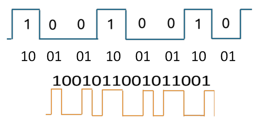
To address this, additional bits are added to the data: A 1 is transmitted as ‘10’ and a 0 as ‘01.’
This ensures that there are a significant number of transitions, which allows the receiving unit to maintain a synchronization between the clock and the data.
In the previous example, this method has been used, and it will see a significantly higher number of transitions:
Continuing with this example, if the relay on the left is transmitting the data and the clock, it will send the data with the clock embedded, and the relay on the right of the diagram will receive the data and recover the clock. This clock will be used to send any data on the reverse channel.
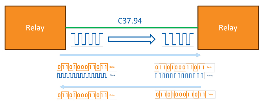
Note that in setting this up, one device will be designated as sourcing the clock, and the other as receiving the clock.
Real-Time Clock Synchronization
A key part of a Teleprotection system is the synchronization of the relays using accurate real-time clocks based on accurate oscillator-based timing.
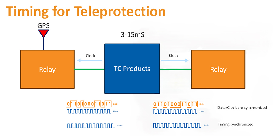
This is commonly done using GPS-based devices, as shown in the following diagram:
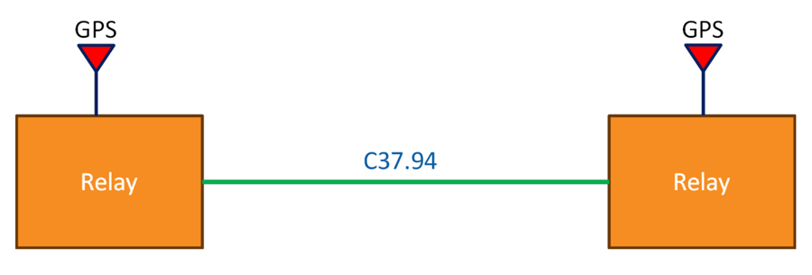
The accuracy provided by the GPS device allows the clocks in both devices to maintain very close synchronization.
However, in some solutions, the C37.94 signaling is used to synchronize devices.
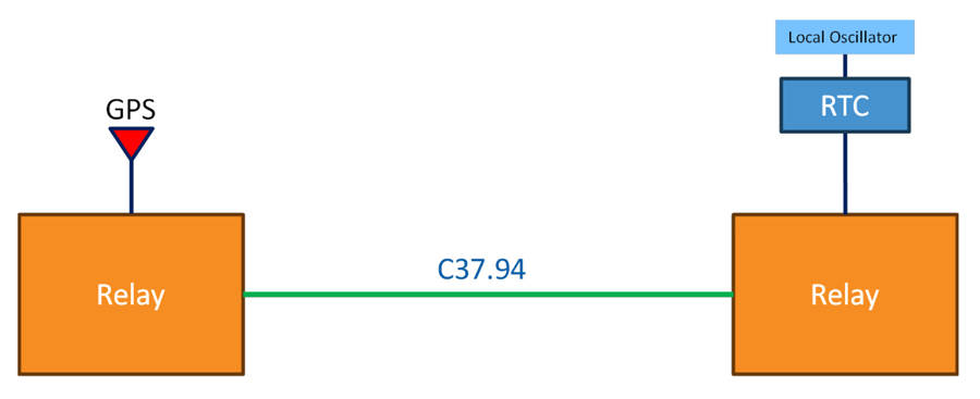
In this case, the accuracy is provided to the relay on the left, but the other relay is using an internal oscillator and real-time clock that is not synchronized. Left in this state, the local oscillator (which is not as accurate as a GPS-based solution) will drift, meaning that any time stamping will be inaccurate.
A solution to this is to synchronize using the clock of the C37.94:
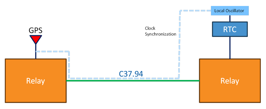
Because the relay on the left of the diagram is time synchronized, the clocking that is used for the C37.94 can also be very accurate; as a result, the retrieved clock can be used to synchronize the real-time clock in the second relay.
Note that although there is a ‘clock’ in the C37.94, there isn’t any time information being passed over the C37.94; it is simply being used to synchronize the relays to the single central synchronizing frequency source (in this case, GPS). This method has commonly been used in the Utility industry.
Adding Devices into the System
Now, this paper will discuss the impact of putting some additional devices into the system, such as the TC3846-2:
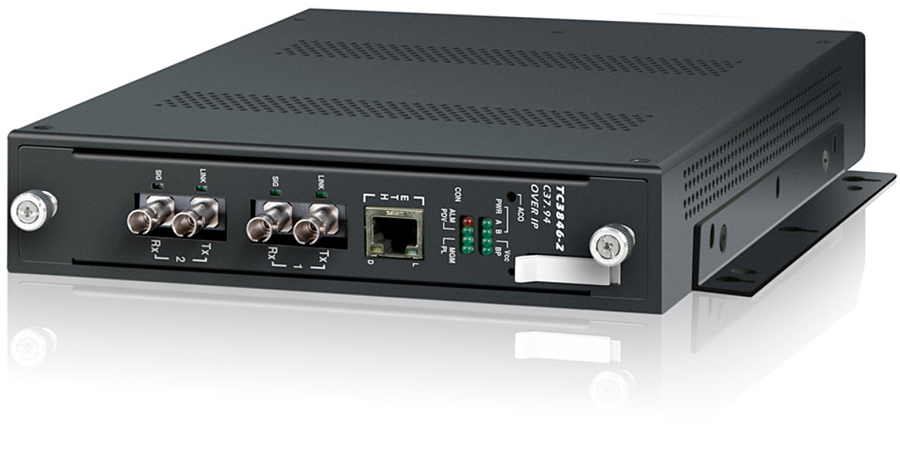
This allows for C37.94 circuits to be transported over Ethernet:
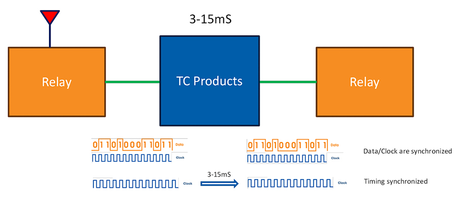
As with all converters that transport circuits over Ethernet, they do introduce delay into this transmission, but this delay does not impact the synchronization between the C37.94 data and clock. Consequently, the data will be transmitted and received with very high accuracy.
However, when looking at the C37.94 signal being used for synchronization between devices, it needs to be investigated whether the C337.94 clock that is recovered can be used. In this case, the issue is that there can be a delay between the data that is transmitted and that which is received. This can be to the order of 3 to 15 milliseconds, depending on the IP network.
Although this is a significant amount of time, in reality, this does not impact the synchronization, as the clock is a square wave that does not carry time positioning data, so once received, the maximum difference between a transmitted clock and the received clock will be a maximum of +/- one half of a cycle of the clock.
The clock is 2.048MHz, so a clock cycle is 488 nanoseconds, and the maximum time displacement is +/-244 nanoseconds.
Now, there is one other setup that can be used, but it has the potential to create the most confusion.
Setting the Devices
Ordinarily, one device is set up such that it generates the clock, and one is set such that it receives the clock.
However, with the additional devices, you can set the devices so that (in this case) the TC3846-2 generates the clock and the other two devices receive the clock.
This will continue to work for the data, as the clock will still be synchronized with the data being transmitted, so the data will continue to be sent and received with the usual very high degree of reliability.
However, when the C37.94 clock is being used to synchronize the relays, this will be reliant on the accuracy of the TC3846-2 device. This is designed to meet the C37.94 standard, so it will only be accurate to 1 PMM (or Part Per Million) guaranteed.
While this is perfect for transmission of C37.94 data, in the use of the synchronization between relays, this may not be entirely accurate enough. The recommendation is that the clock source be set such that the relay with the accurate frequency input is set to generate the clock.
The Impact of Daisy-Chaining
The last consideration is that if devices are to be synchronized, and they are daisy-chained, that any inaccuracy in the timing will compound, as shown in the following diagram:
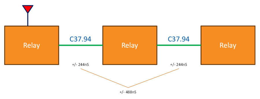
Devices further down the chain will be working with a clock signal that has significantly more jitter than the one received by the first device. This makes it more difficult for later devices to determine the true clock edge, which can lead to data errors.
Propagation and aperture delays
In addition to signal quality degradation, the physical and electronic characteristics of the devices and cables introduce delays that compound with each device in the chain.
- Propagation delay: This is the time it takes for the clock signal to travel from one device to the next. In a daisy-chain, the propagation delay from the master to the last slave is the sum of all the individual cable delays.
- Aperture delay: Each slave device in the chain introduces an additional, well-defined delay as it receives and retransmits the clock signal. While this delay can sometimes be accounted for, it still contributes to the overall timing offset.
- Increasing time skew: The accumulating delays result in a time skew, or increasing timing difference, between the devices further down the chain and the original master clock.
To avoid the compounded inaccuracy of a daisy chain, a star network topology may be recommended for clock synchronization.
Ask a question