Introduction
While TC Communications has deployed many solutions where Mirrored Bits* over Ethernet is used, there are common questions around how using Ethernet impact operations.
The top 3 common areas include:
- Compatibility
- Security
- Latency
This application note will address all three areas and show how TC Communications' products are used to provide solutions.
*Note: "Mirrored Bits®" is a registered trademark of Schweitzer Engineering Laboratories Inc. For more information on Mirrored Bits see Addendum.
The serial format is proprietary and so many serial over Ethernet devices do not recognize the serial format of the Mirrored Bits protocol.

Traditional serial/Ethernet converters receive serial data, buffer the received data and then transmits the data as a packet. Once received, the data is un-packetized and reconstituted as serial data. Since the Mirrored Bits protocol is proprietary, it may not be recognized by the serial Ethernet device.
TC Communications addresses this by not decoding the serial data but instead samples the waveform as shown in the following diagrams.

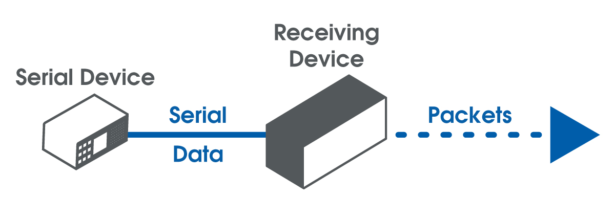
By sampling the waveform, the results have clear benefits:
1. Compatibility
Serial data stream is being sampled with no data being decoded results in complete compatibility with all serial data formats.
2. Security
To enhance the security link, the data stream is not being decoded and no copy of data transmits to TC Communications devices.
Data is being sampled and transmitted continuously so with the TC Communications solution, it is statistically likely that Mirrored Bits data will be split between Ethernet packets.
3. Latency
Having addressed compatibility and security, the remaining question that is commonly asked is on latency over an Ethernet link.
When considering the latency for an Ethernet link, there are 3 key variables to consider:
- Ethernet link latency
- Packet delay variation/Buffery
- Digitization delay
To correctly calculate the link latency we use the following formula:
Overall link latency = Ethernet link latency + PDV/Buffer + Digitalization delay
TOLL = TELL + TPDV/BUFF + TDD
Where
TOLL = Overall Link Latency
TELL = Ethernet Link Latency
TPDV/BUFF = PDV Buffer Size
TDD = Digitalization Delay
Ethernet link latency
Each Ethernet link has an inherent latency from one point to another. This forms part of the overall latency and is essentially constant.
When choosing commercial Ethernet links. It is important to choose one with minimal delay to minimize the overall latency. A network latency of around 2ms is ideal.
Packet delay variations
Each link also has packet delay variation or jitter.
Consider this additional to the link latency, PDV is a variable where the PDV is expressed as a maximum.
So if PDV is expressed as 1ms, the maximum, it can and often will be less than this, but for calculation purposes, we are considering the worst case scenario or maximum number.
Additionally, to ensure a consistent latency and to make sure that waveforms are correctly reconstructed. without gaps and omissions, a buffer is used. Typically, this buffer is slightly larger than the PDV to allow for any excessive PDV.
The buffer also compensates for packet size. Since packet size is variable and impacts both link delay and bandwidth.
Generally, the larger the packet, the longer the delay and lower the bandwidth. The opposite holds true where smaller packets create lower delays and increases the bandwidth.
Digitization delay
While small, there is a constant delay caused by digitizing the incoming waveform and assembling the data into a packet.
For example, if the waveform is being sampled at 4 times the baud rate, the baud rate is 9600 bps, packet payload size is 32 bytes, then the sample rate is 38400 Hz, one byte per sample means 32 samples in a packet.
Digitalization delay = # of samples/sample rate
=32 (samples)/ 38400 (sample rate)
=0.833 ms
In another example, we have a data payload of 8 bytes. The delay is as follows:
Digitalization delay = 8/38400=0.2ms
Typical link delays
The following table shows link delays due to PDV/Buffer.
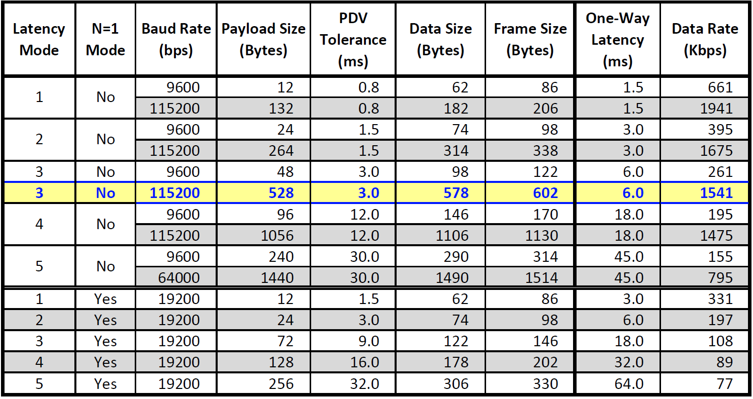
In Blue is the typical setting for a link, however you will see that latency mode 1 can be set for 1.5mS latency although this is at the expense of slightly higher bandwidth requirements.
In addition, the overall link delay and the digitalization delay results in a typical of overall link delay values. These delay values are completely compatible with teleprotection requirements which is why TC Communications' solutions are the products of choice for U.S. Utilities transitioning to Ethernet based transport.
Conclusion
This application note considered 3 major areas where Utility users question the suitability of Ethernet based solutions for Mirrored Bits based teleprotection circuits.
1. Compatibility
By over sampling the incoming waveform rather than decoding the serial data, TC Communications provide complete compatibility for Mirrored Bits solutions.
2. Security
As the serial data stream is not decoded, no teleprotection data is stored, which means no cybersecurity threat is present.
3. Latency
By choosing a quality network and setting the interface parameters suitably it is very simple to ensure that the overall network latency is kept to a minimum and is suitable for all uses in teleprotection networks.
Related
Solutions


Addendum
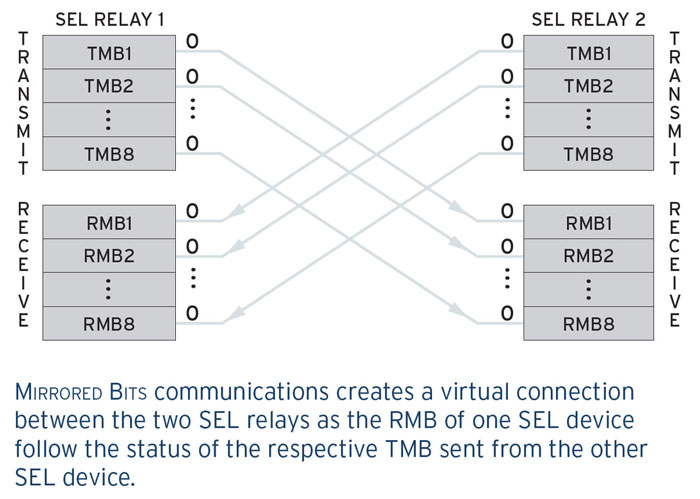
Mirrored Bits operation
SEL relays can use Mirrored Bits as described below:
"Older communication methods that rely on hard contacts to transfer system status data are complicated, expensive, and have limited capabilities. Mirrored Bits communications eliminates those challenges. In a system using Mirrored Bits, the RMBs of one relay track the status of the respective TMBs sent from another relay. You can use the RMBs in programmable logic to implement transfer tripping, blocking and interlocking; permissive schemes; direct control; or any function that would otherwise be performed with a programmable contact input. Each of the relays in scheme repeatedly sends and receives the digital logic message while continually monitoring the received message integrity. An internal monitoring point asserts when a good message is received and de-asserts immediately on detection of a bad message. If a message is compromised, the system will alarm operators and enable them to access relay channel monitoring reports."
From: Mirrored Bits® Communications - SEL PF00048
Interested in similar content? Subscribe to our mailing list.